

Description
I recently acquired a 2012 Auris as a replacement for an Avensis, and generally like the car. However, it has the analogue instruments (non optitron) and one immediate irritation was that, unlike the Avensis, the instrument lighting was not on in daylight, and on grey winter days I found the instruments harder to see. On dull days I found myself putting on the sidelights simply so I could see how fast I was going.
I thought it should be possible to do a simple mod to get the instrument lights to come on with the ignition - I could not find any reference to anyone else doing this, but did find several other complaints about the dim instruments.
This is my solution. First - the usual disclaimer - you follow this guide at your own risk, and I take no responsibility for errors or damage to your car, and you may invalidate any guarantee with this work. I would also strongly suggest that you use a multimeter to check that the connector pins and wire colours on your car correspond with those in this guide.
You need a little electronic/electrical experience, a soldering iron, some heat shrink sleeve, and a couple of diodes. A multimeter is also necessary to do the checks mentioned above.
The theory was that if I could find the +12 volt lighting feed to the instruments then, with the addition of a couple of diodes, I could add an ignition switched feed as well.
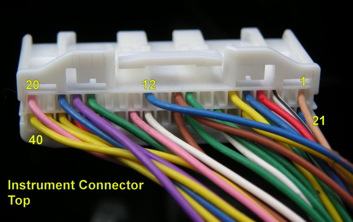
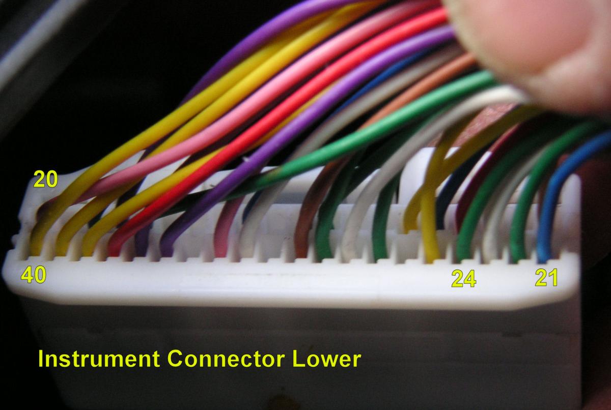
First step was to remove the speedo unit and hood - pull the hood towards you while sitting in the drivers seat, and then remove the four screws holding the instrument unit. After unplugging the unit I found a 40 pin connector, with 29 pins used. Toyota pin numbering seems to be (looking at the mating face of the connector, clip at the top) top row left to right 1 onward, then second row etc. Using this scheme means that from the cable side the top row has pin number 1 top right - see pictures with numbers added. References in this guide are to the pin number and the relevant wire colour in the photos.
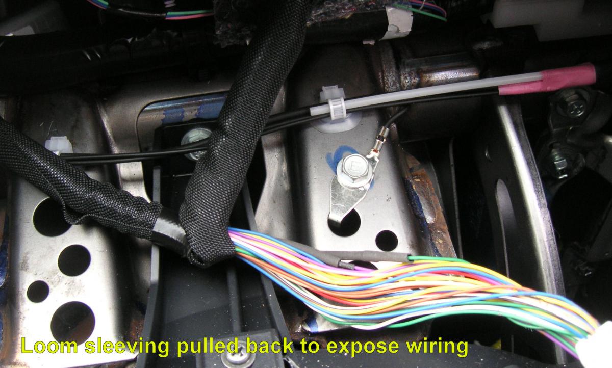
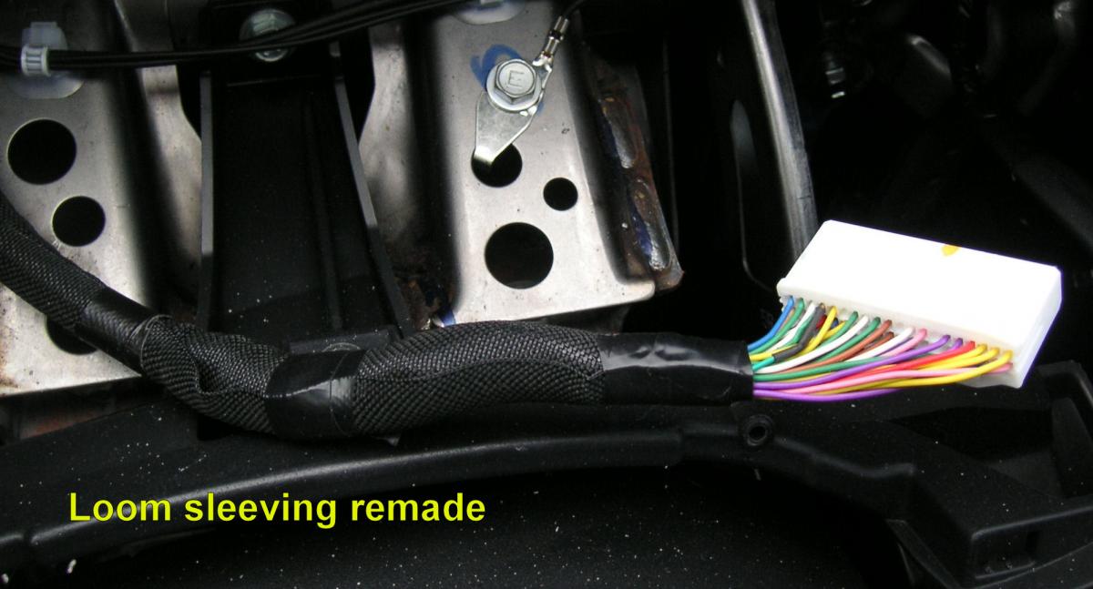
The cable loom is covered in a strip of black fabric wrapped and taped - so I removed the end tape and pulled back the cover to provide access to the individual wires. This also meant that the mods could be done further down the loom, and the cover replaced later.
Using a probe of stiff thin brass wire I looked for appropriate voltages at the back of the connector shell, and found:
+12V permanently on - pin 32 white
+12V ign switched - 4 pins, including pin 12 blue.
+12V (approx) with lights on - pins 16 green, 17 purple, and 24 green.
The switched light feed was what I was looking for, but having three was unhelpful.... I couldn't think of an alternative to cutting wires and seeing the effect.
I started with Pin 16 Green, and found that it lit the green "lights on" icon in the tachometer.
Pin 17 Purple appeared to have no discernible effect....
Pin 24 Green was the right one, and controlled the instrument background lighting. Measuring the current showed 13mA, so it looks as though this is an enable feed to a switch (probably semiconductor) in the speedo, rather than feeding the lights directly, in which case I would have expected a higher current reading even with LEDs.
I resoldered the cut wires to pins 16 and 17, and heatshrinked the joints. It’s a shame that the one I wanted wasn't first! You can see the repairs in some of the photos.
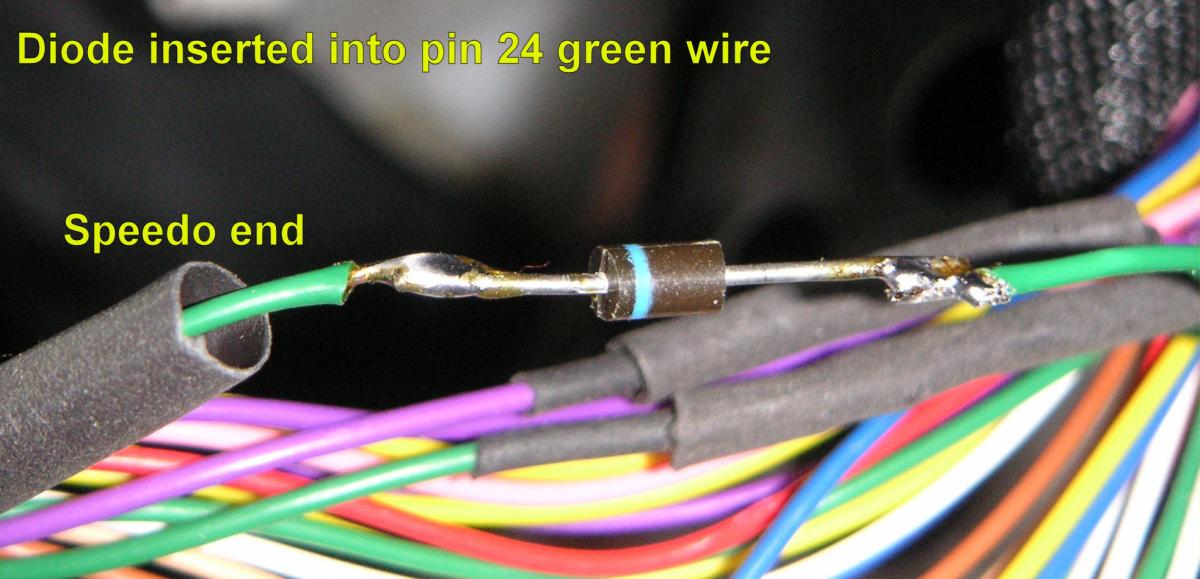
I inserted an IN4006 diode into the cut green wire from pin 24, and heatshrinked the diode and joints. NB - important - the diode band is nearest to the speedo. Any diode around 1 amp and at least 100 volts rating should do here - I had IN4006’s to hand.
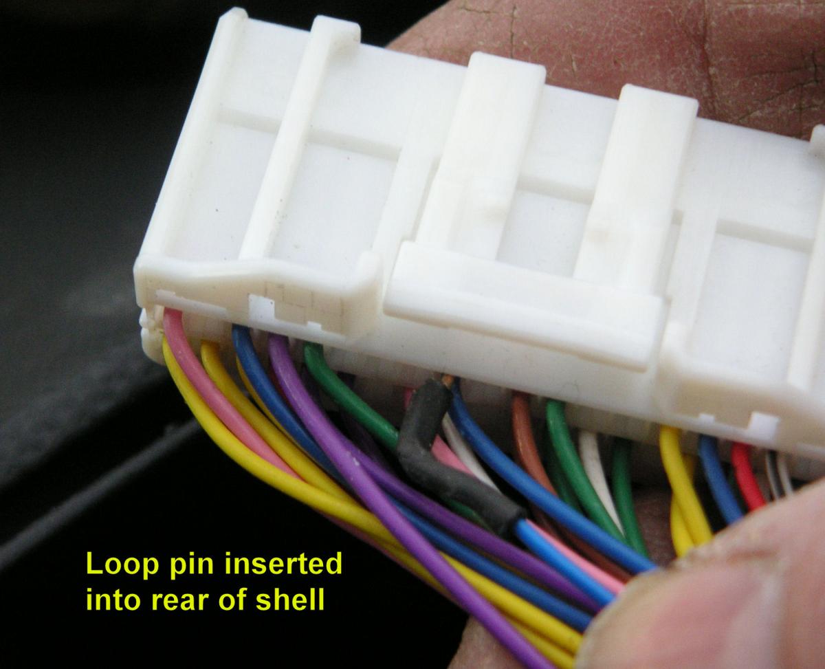
Next I needed to add a feed of ign switched volts, and chose pin 12 blue, simply because I had some wire of that colour. I've found that a good way to make non permanent connections is to insert a stiff wire of a suitable diameter into the back of a connector shell, where it sits snugly next to the crimped terminal - this seems crude, but appears to work well, and is removable without trace if needed. About six inches of blue and green wire was soldered to each end of another IN4006 diode, a short piece of brass wire was added at the ends, and all heatshrinked. This can be seen in two pictures - NB note diode polarity.
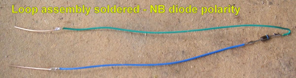
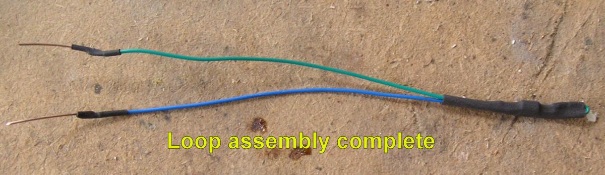
This "loop" cable was then plugged into the back of pins 12 and 24, matching the wire colours. Trim the stiff wire ends until they plug neatly and firmly into the rear of the connector shell. The second diode in the loop assembly was tucked back down the loom, and the covering replaced
 .
.
There is no real sign that anything has been done, unless you look very closely at the back of the connector.
The instrument lighting now behaves as before, so will come on with lights on/ign off, but is additionally on all the time with ign on. Doing it like this means that removing the loop assembly puts the car back to its original state - without needing to remove the inserted diode in pin 24 wire. Also, if the loop pins should work loose, you still have the original instrument light function.
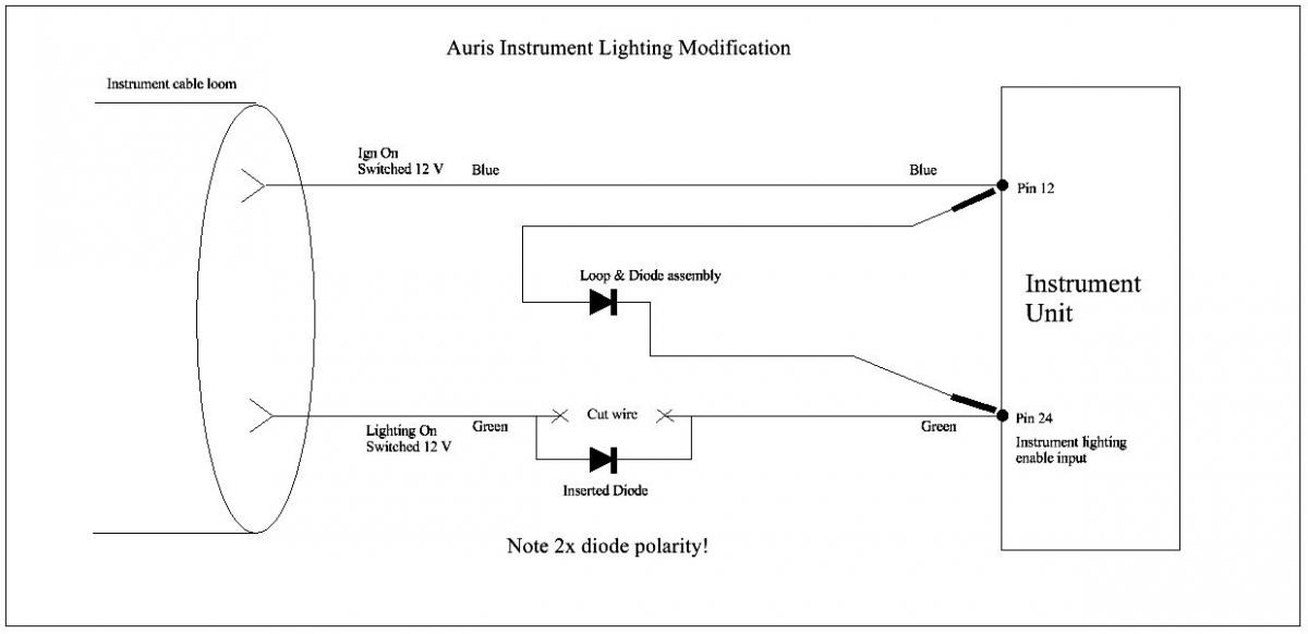
The circuit diagram of the mod follows. 12 volts is fed from both the original lights feed, and the borrowed ignition feed, through the two diodes, to the speedo lighting enable input. The diodes prevent the two 12V feeds sending current to each other - vital as I have no way of telling how these two switched voltages have been derived. DO NOT omit the diodes, and double check the polarity!
It would be nice to have full brightness during the day, and dimmed at night, but this would involve a whole different level of complexity. I found that one level of brightness down from full is a decent compromise for both day and night. On a bright day the background lighting doesn’t show at all, but if you move under dense trees etc it is then visible, and makes the instruments much more readable.
With the analogue instruments I think this is a worthwhile mod, and I’m surprised that Toyota have not made this a (software?) option.
Diodes, heatshrink, and coloured wire are available from Rapid Electronics http://www.rapidonline.com/ - or other suppliers.
Extra Fields
General
-
Time Taken?
2 hours being very cautious
-
Tools Used?
Multimeter, soldering iron, solder,
-
List Parts Used?
2x diodes rated 1 amp & 100 volt or higher <br />Thin insulated wire <br />Stiff brass wire<br />Heatshrink tubing
-
Costs?
minimal
-
Difficulty Level? 1-5
With some electronics experience 2-3

Recommended Comments
Join the conversation
You can post now and register later. If you have an account, sign in now to post with your account.