Leaderboard


Popular Content
Showing content with the highest reputation on 11/16/2015 in all areas
-
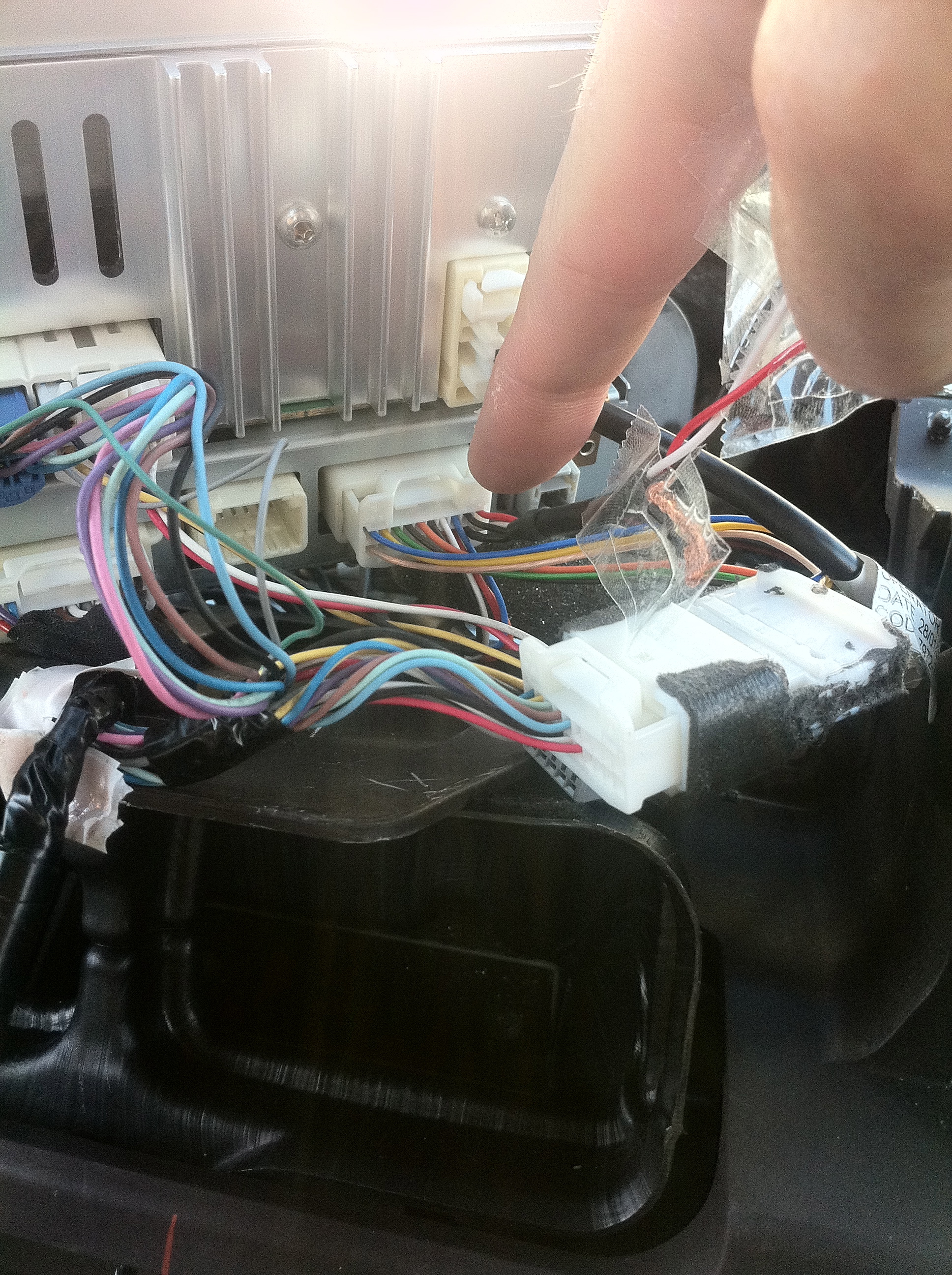
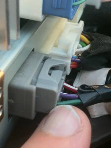
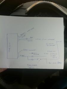
Hi all I'm putting this information on here for people who may wish to fit an aftermarket camera to their TNS510 at a fraction of the cost of an, IMO MR T's ugly one. The reason for putting it on here is that it gets picked up by the google search engine. I could find no information what so ever about the TNS510 so all the work has been done by me and many hours of experimentation to see how it functions. OVER VIEW For the TNS510 to accept a camera input, a few things have to occur. Firstly, there are 4 connections at the rear of the unit pins 27,28,29 and 30. They are colour coded, RED, WHITE, BLACK and screen (braided wire) Now you would think that they are obvious connections but they are not. When the unit is powered up from !st and /or 2nd stage ignition, the unit produces 6v on the BLACK wire and the negative side being the WHITE wire. Now unless you are going to feed MR T's camera which is an unusually 6volt camera, these 2 wires can be ignored,either taped up or left in their connector sockets. The one's your interested in are the screen and the RED wire. The RED wire is Video In and the screen it what it is, the shield for the video signal. This is not the end of the story. For the unit to switch into camera mode, a 12volt supply is fed from the ECU via control function by actuating reverse gear. This is where I had problems and upset my ECU.Normally 12volts would have been switched when the switch in the reverse gear lever was actuated rather than a low level command the ECU. By just using the RED and screen wires and powering the camera from a switched 12volt supply (i.e the auxiliary socket below the A/C consul via fuse) all works fine when you choose reverse. The problem was I wanted to switch the camera on whilst not in reverse. When the gear is put in reverse, the 12volt switching voltage is sent from the ECU on a green wire in a grey socket to the unit. One would think by emulating this 12volts you could switch the camera on.Well that is what happens except it brings up engine management light, air bag light and VSC alarms!!! whats worse is that by removing this 12volts the alarms still remain and switching the ignition on and off doesn't clear them.!!!. Fortunately, by removing the battery for 30mins resets the ECU and resets stored memory. So what do we do? You need to make sure you have cut back and revealed about 4inches of the green wire and cut it. Solder a 1n4006 diode between the 2 ends you have just cut. Anode towards the ECU feed and the Cathode (stripe) towards the unit as in my diagram. Also soldered to the unit end is the switched 12volt feed again via a 1N4006 diode as per my diagram. Now with the first stage of the ignition on you can operate your bypass switch (which i mounted on a spare blanking plate on my dash board and illuminated it) and the camera will come on and no nasty alarms. Works perfectly. The diodes are included to stop your switched bypass 12volt feed going back down to the ECU and upsetting it but only going to the TNS510 to switch it into video mode. A couple of other bits of information. The 6v that you are not using, is only active for 30 seconds. I suspect MR T must think you must of reversed by then. Also the screen will not switch into video mode even with the 12 volts on the green wire if the TNS510 doesn't see a video signal from the camera So if your fuse blows feeding 12volts to your camera, you won't get a blank screen, you will see no change on the screen All clear? Good I'm not expecting lots of comments its really up hear for people to search and find and hopefully help them David

 1 point
 -
Hi, The 3 most common faults is: wheel bearings. in electric mode, radio off, windows down, cruise at 20-30mph on a smooth road and see if there is any unusaul noise. - each new wheel bearing from Mr T will set you back approx £400 per wheel Intermediate shaft & steering column - when turning the steering wheel, try and listen and feel for a knocking noise. If there us also a lot of play then this is signs of a problem. New parts and labour £1800. EGR vavle - this one is quite hard to check, the car would shake and shudder which was very very intermittent. I bought my car at 30k on the clock and it hapened once between 30-40k. bewteen 40-50k maybe 2 or 3 times. 50-60k again 2-3 times. 60-61k more times than i could count and I managed to take a video of the problem. New valve and manifold clean cost £350. I have been very unlucky and experienced all 3 of the most common faults. Out of warranty Mr T was kind enough to make a contribution each time. Dont let this put you off, they have sold millions of this car, i was just very unlucky.1 point
-
Did it have any long term affects on the engine? Thanks for the reply. Not so far as I know. But being a petrol engine, and before most of the emissions controls, it was quite simple.1 point
-
OK, I have finally switched to winter tyres on 16's and the difference is huuuuuuuuge! The ride is way more comfortable compared to the 17's. I can also confirm that Auris that came on 17's has bigger brakes and can't be fitted with 15-inch wheels. After I fitted the 16's, there was only a couple of millimeters space left between wheel and caliper, so absolutely not possible!1 point
-
Rather than plump for an internet diagnosis it might be worth your while to have a local independant mechanic have a look at them. A thorough strip, clean and inspection should uncover the actual fault - if there is one. In the meantime if you want to reassure yourself that the brakes work well, find a nice quiet road and give them a good stomping at about 20 mph. If the ABS kicks in then your brakes are still strong, if a little strange just before stopping.1 point
-
I used a Pal one but people have use a kind of hybrid of both. If your using a 12v available just about everywhere for £5. Because of the way the Tns510 looks for video there is a small time window for it to see video from the camera. The original reversing camera from Toyota is 6v and is supplied to the camera from the Tns510 when reverse gear is selected. In about a quarter of a second after power is supplied, the Tns510 is looking for video. The screen blanks for a split second. If it doesnt see video it drops back to map. The very best way to power your 12v camera is to power it from the ACC supply i.e when the ignition is on. You can use the back of the Aux /cigarette lighter socket. This ensures the camera is sending video constantly to the Tns510 but only displays it when reverse is selected. Dont worry it wont wear out mine is fine these past 4yrs. Take a look at the installation instructions of the original toyota camera. Behind the Tns520 there is a sleeved cable with 2x black wires, 1x red and 1x white one. The video from the camera goes to this cable. The video screen goes to either of the black wires and the centre video wire goes to the red wire. The white wire is not used and has 6v on it when reverse is selected so tape it up out of the way. Dont be tempted to power the camera off the reversing light because when reverse is selected there is a small delay for the light to be powered and by the time the camera gets powered up, its missed the window the Tns510 was looking for video and drops back to map. Simples David1 point
-
Hi I am assuming your looking to fit a rearviev camera. Have you seen the installation instructions for installing the original Toyota camera? Not only does it come with the camera and mounting but also the grey plug with 3 wires on it which have to be connected to various points on tbe connectors under the kick cover in the footwells. These wires put conditions on the grey socket for the camera to operate under certain conditions. When reverse is selected, a control signal is sent from tbe gearbox to the ecu which in turn sends a 12v signal on the green wire on the grey plug. This momentarily puts the tns510 into A/V mode and looks for a video signal. If in 1second it doesnt see a video signal it ignors the 12v command and reverts back to map or what ever it was on before the reverse gear was selected. One note, you dont need to go into the "secret menu" when installing a camera. You can buy the grey plug withetge wires on it seperatly. Look for the tns510 installation guide for the part number. Pm me if with a phone number if you want a chat about it David Just found the part number for the lead you need PZ445-00333-00 Think it was about £151 point